Multiple-Device Synchronization Using USB or PXI Devices
You can synchronize multiple devices in a DataAcquisition using a shared scan clock and shared start trigger. You can synchronize devices using either PFI or RTSI lines.
This concept piece is apparently designed with left-handed mobile users in mind. But there are no details about what's different on creator Bence Bogar's design site. The little thumb wheel is right there, on the right-hand side, exactly where it is on all those fancy Blackberry things. It's pretty much symmetrical. It looks like a perfectly normal iPhone rip-off. Also related to RF test, Aeroflex’s Mr. Carey described how PXI improved throughput and test coverage for smart phones, “Modern chips used in mobile phones have vendor-specific test modes to help accelerate various aspects of test. The PXI‑8840 includes two 10/100/1000BASE‑TX (Gigabit) Ethernet ports, two USB 3.0 ports, four USB 2.0 ports, as well as an integrated hard drive, serial port, and other peripheral I/O. VXI and PXI spectrum analyzers are available, if these rack systems are being used. The spectrum analyzer is an essential item of test equipment used in RF test and RF design laboratories where they are used extensively, but they are not normally found outside these environments, although audio analysers are used for some specific tests.
Requirement
You must register your RTSI cable using the National Instruments™ Measurement & Automation Explorer.
Acquire Synchronized Data Using USB Devices
This example shows how to acquire synchronized voltage data from multiple devices using a shared start trigger and a shared scan clock. Analog input channels on all three devices are connected to the same function generator.
Create a DataAcquisition and add one voltage input channel from each device:
NI USB-6211 with device ID
Dev1NI USB 6218 with device ID
Dev2NI USB 6255 with device ID
Dev3
Choose terminal PFI4 on Dev1 as the start trigger source. Connect the trigger source to the destination terminals PFI0 on Dev2 and PFI0 on Dev3.
Choose terminal PFI5 on Dev1 as the scan clock source. Connect it to destination terminals PFI1 on Dev2, and PFI1 on Dev3.
Acquire data and assign it to dataIn.
Plot the data.
All channels are connected to the same function generator, so the plot displays overlapping signals, indicating synchronization.
Synchronize Counter Outputs from Multiple Devices

This example shows how to synchronize the start trigger of counter output operations from two channels on different devices.
This example uses two USB or PCI devices, but could be modified for channels across CompactDAQ or PXI chassis. If you have counter output CompactDAQ modules in the same chassis, it is not necessary to call addtrigger; but it is required for multiple modules in the same PXI chassis.
Synchronize DSA PXI Devices Using AutoSyncDSA
This example shows how to acquire synchronized data from two Dynamic Signal Analyzer (DSA) PXI devices, NI PXI-4462 and NI PXI-4461, using the AutoSyncDSA property.
Mobile Phones Definition

Create a DataAcquisition and add one voltage analog input channel from each of the two PXI devices
Acquire data in the foreground without synchronizing the channels:
The data returned is not synchronized.
Synchronize the two channels using the AutoSyncDSA property:
Acquire data in the foreground and plot it:
Pxi Mobile Phones Wireless
The data is now synchronized.
Acquire Synchronized Data Using PXI Devices
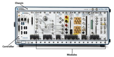
This example shows how to acquire voltage data from two PXI devices on the same chassis, using a shared start trigger to synchronize operations within your DataAcquisition. PXI devices have a shared reference clock that automatically synchronizes scan clocking. You need to add only start trigger connections to synchronize operations in your DataAcquisition with PXI devices. Analog input channels on all devices are connected to the same function generator.
Create a DataAcquisition and add one voltage input channel from each NI-PXI 4461 device with IDs PXI1Slot2 and PXI1Slot3.
Add a start trigger connection to terminal PXI_Trig0 on PXI1Slot2 and connect it to terminal PXI_Trig0 on PXI1Slot3. PXI cards are connected through the chassis backplane, so you do not have to wire them physically.
Acquire data and assign it to dataIn.
Plot the data.
All channels are connected to the same function generator and have a shared reference clock. The signals overlap, indicating synchronization.

Pxi Mobile Phones App
Related Topics
